The Manifold Assembly: Running multiple items from a single pump
by
, 01-29-2011 at 04:34 AM (25858 Views)
With the return section completed, it was time to build the second section that is called a manifold. It has its own pump, and feeds a few items. The beauty of a manifold is that one external pump takes the place of multiple submersible pumps, and a series of valves provides the user to control flow rates to each item.
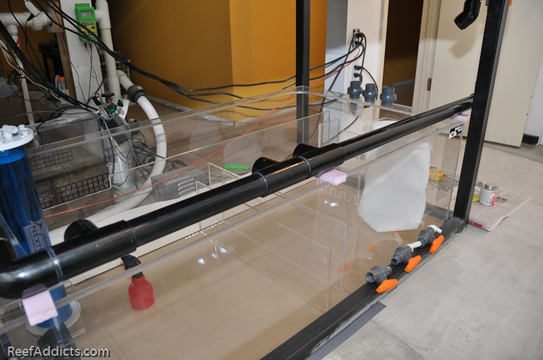
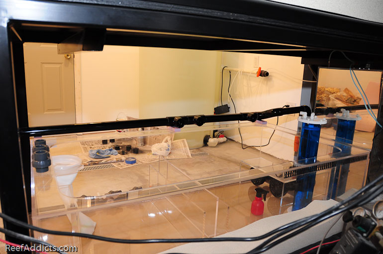
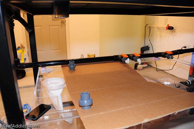
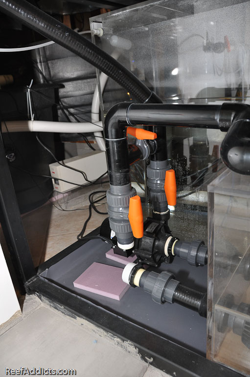
My goal was to run three reactors and a frag tank, and also have it available as a secondary back up to the main return pump if needed. I wanted to run the manifold inside the sump using Uniseals because I'd not seen it done before, but talked myself out of it after the sump was built. Black PVC looks great while it's clean, but once salt creep spreads it wouldn't look good and would be tough to clean. I thought about running it up high over the sump, but felt the valves would be in the way. I thought about running it in front of the sump, but didn't like that either. In the end, I decided to run it along the top flange, hovering about 3/4" above the sump.
In the following pictures, you'll see the full assembly minus the pump itself as that pump is currently in use. It will be moved over very soon.
Where to put the valves was a good question, and I spent some time with each in various places to weigh the pros and cons of working in the sump with them in the way.
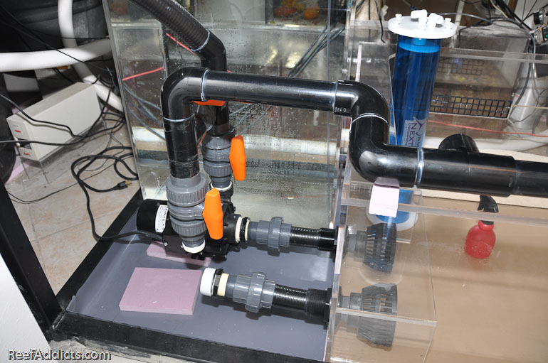
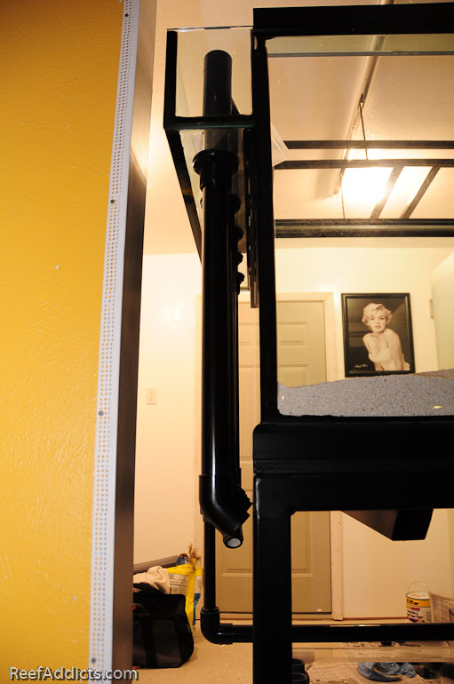
This vertical piece with the DUBV is for the frag tank feed line.
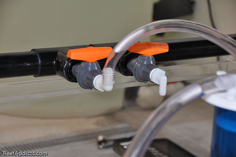
Each valve is a 1" threaded piece. They are very easy to turn, and durable. One for the calcium reactor, one for the NP reactor by NextReef, and one for a carbon reactor.
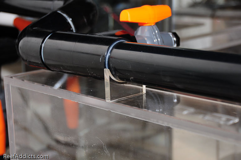
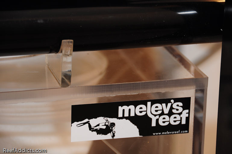
I fabricated a couple of acrylic supports to keep the manifold supported. The entire manifold is made with 1.5" black PVC pipe, and each valve is 1".
If the return pump for the display tank fails, the manifold pump will act as an emergency back up. Whether I'm home or not, a couple of valves can be twisted to redirect flow until I can fix the problem. By closing the valve above the return pump and opening the valve between the two pumps, water will be directed up to keep the reef tank fed with water from the sump.
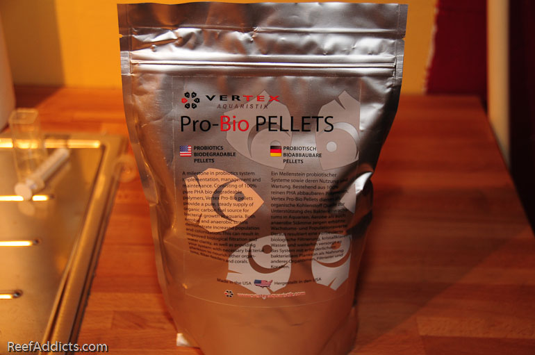
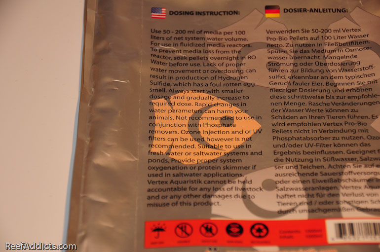
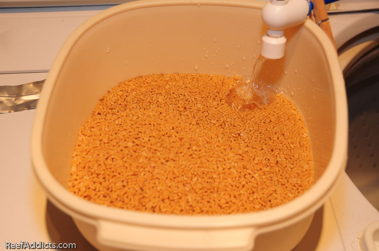
While the manifold slowly came to be, I soaked the Vertex NP pellets in RO water for 24 hours. NP pellets are designed to reduce nitrate and phosphate (thus "NP") from the water continuously. I'm using two pouches (2 liters) for my tank.
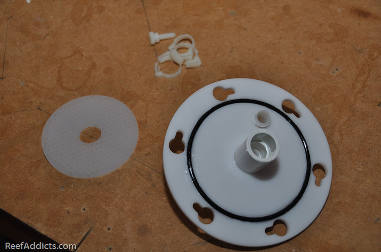
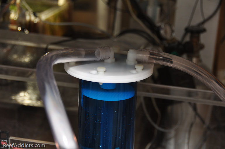
These are going in the NextReef SMR1 XL reactor. I removed the lid, applied silicone grease to the O-ring, and removed the upper perforated plate.
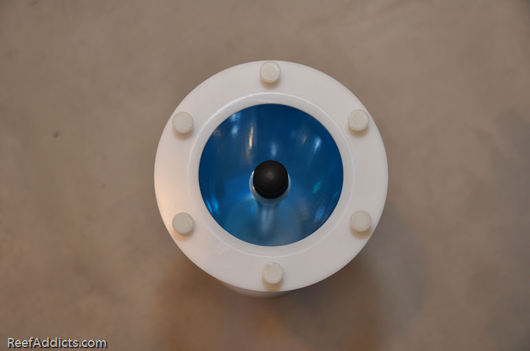
Then I took a handy rubber cap and covered the center tube to avoid spilling pellets in it.
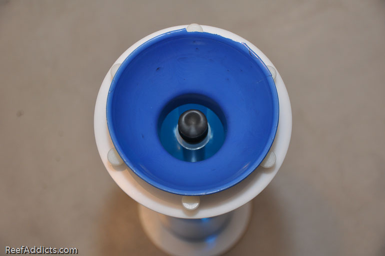
This is a jelly canning funnel that I picked up at the store for $0.99. It's very handy to pour in solid media in various reactors.
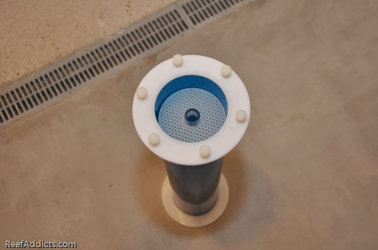
Pouring out the water first, I used a plastic soup ladle to scoop up the NP pellets and pour them into the reactor. Once all the media was added, the upper plate was reinstalled, and the lid screwed down.
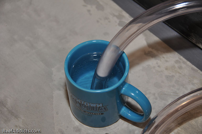
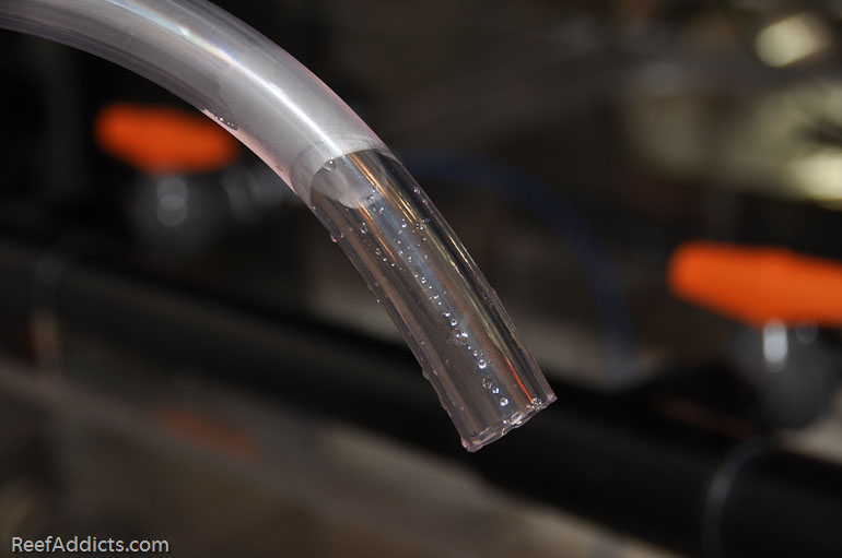
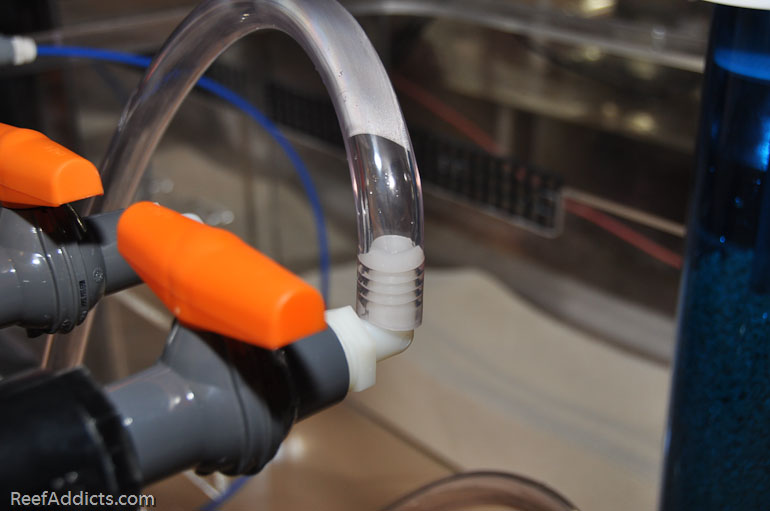
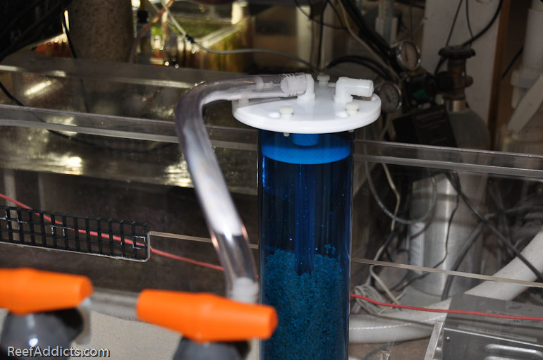
Heating up some water in a coffee mug for two minutes in a microwave, I was able to soften the 5/8" vinyl tubing to fit over the hose barb connections.
Hose clamps are definitely necessary, but I've not found my stash yet.
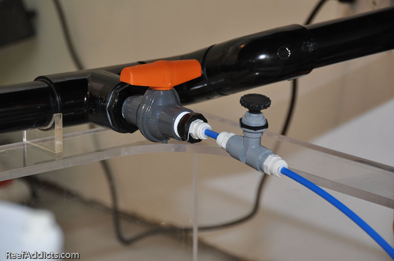
For the calcium reactor, I'm using this little 1/4" gate valve to dial in the perfect flow rate into the calcium reactor. I wanted to use a 1/4" nipple but couldn't find it anywhere locally.
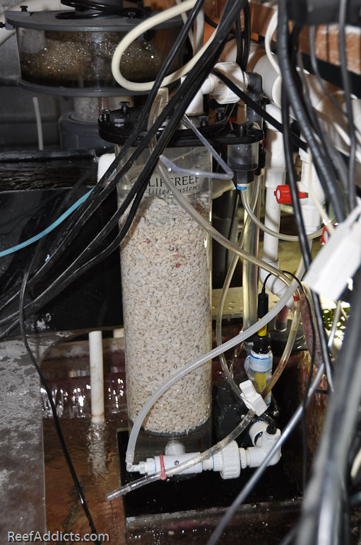
I cleaned out the calcium reactor today, and refilled it with more media. It is ready for the new sump, and will move over by the end of the weekend. When it moves, I'll change out that lower hosebarb fitting for a JG (John Guest) fitting so I can easily insert the blue 1/4" tubing pictured above.
The carbon reactor is a Two Little Fishies Phosban reactor. It'll stand in the sump and a short length of 1/2" vinyl tubing will run from the third valve to reactor. Carbon maintains water clarity, and I change it often.
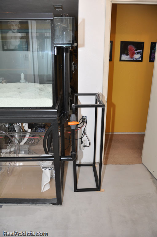
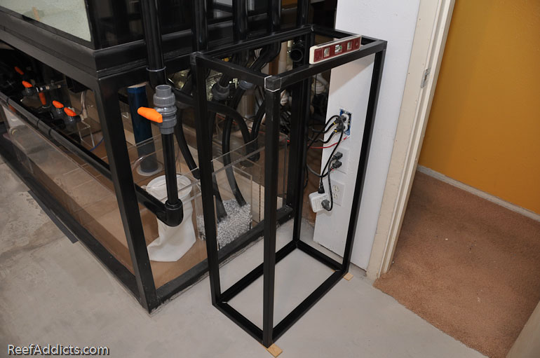
The final valve runs to the future frag tank that stands at the end of the display. The stand is made from EzTube, and the frag tank will be 21" x 12" x 8".
