View RSS Feed

melev

Plumbing: Return assembly with Penductors

Rating: 7 votes, 4.86 average.
With all the months of planning, I still found myself thinking about how I wanted the plumbing to be, pondering on what would be the ideal layout that wouldn't result in having to make changes and modifications later. I had some crazy ideas in mind originally, but modified them some.

The principle is simple: Water drains into the sump. Water goes back up to the display tank. Avoid too many turns and fittings, and keep it looking clean.

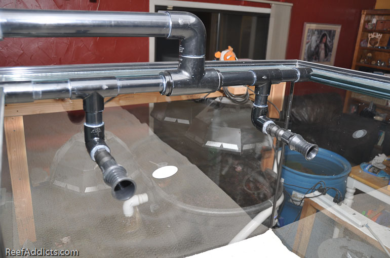
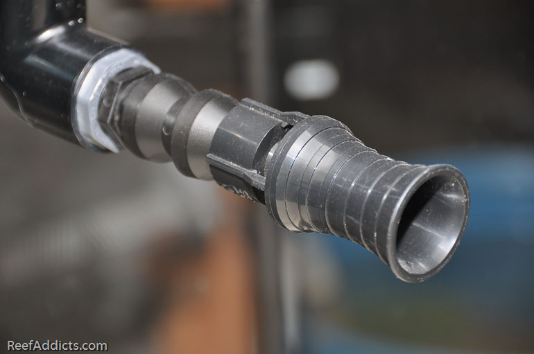
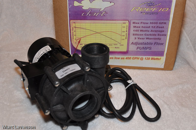
The return assembly was a big deal all by itself. Pete gave me a great idea of how to secure it between the eurobracing of the tank, and I just had to come up with a working creation. Putting the Sequence Dart pump underneath the area where the twin returns would be, it limited the total plumbing significantly. For this tank, I'm using Penductors (flow accelerators).

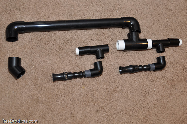
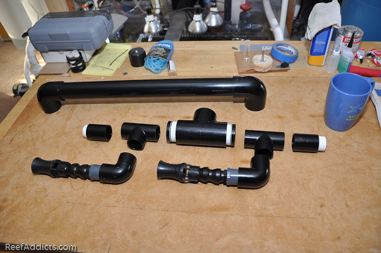
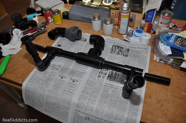
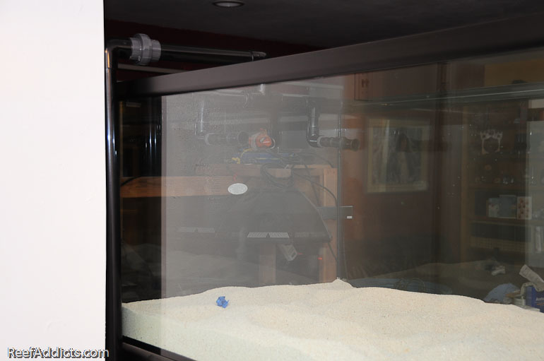
First I laid out the pieces to visually see what it was supposed to look like.


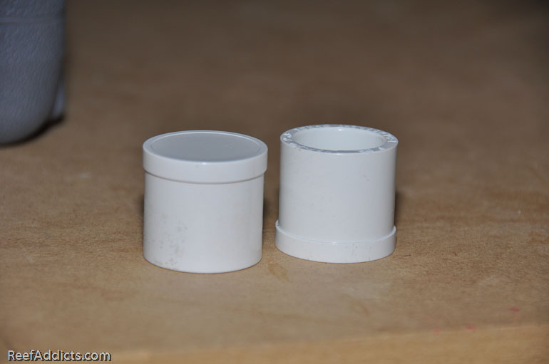
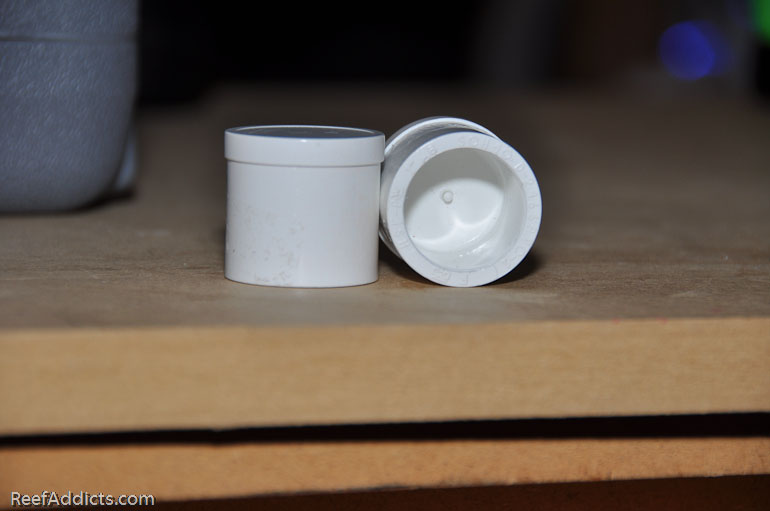
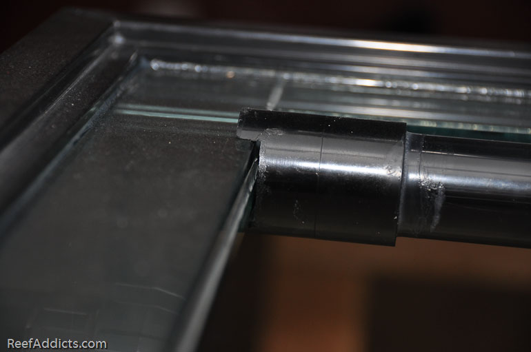
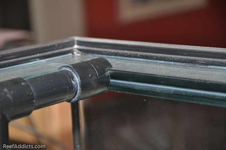
The end pieces that would press against the eurobracing had to be notched, and water couldn't come out of those ends of course. Pete had seen some reverse plugs that he felt were perfect for the job, but I couldn't use those since my parts were slip fittings. I found alternatives, but it involved a Dremel with a sanding bit to create the piece I needed.


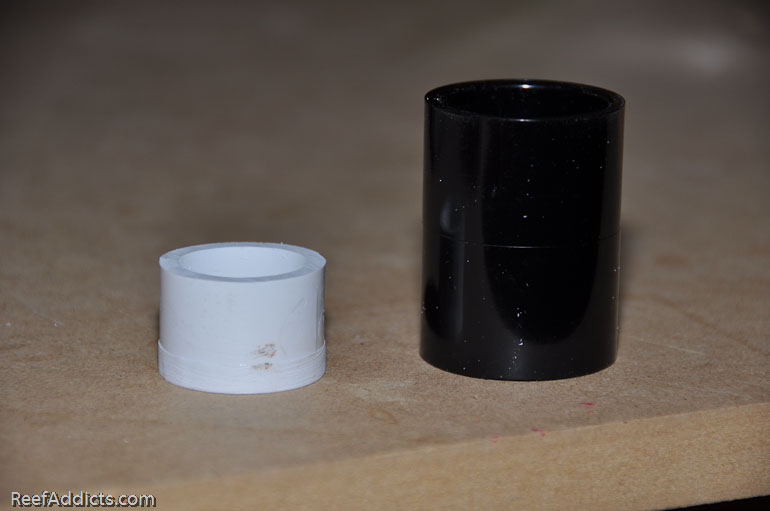
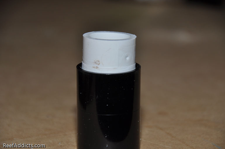
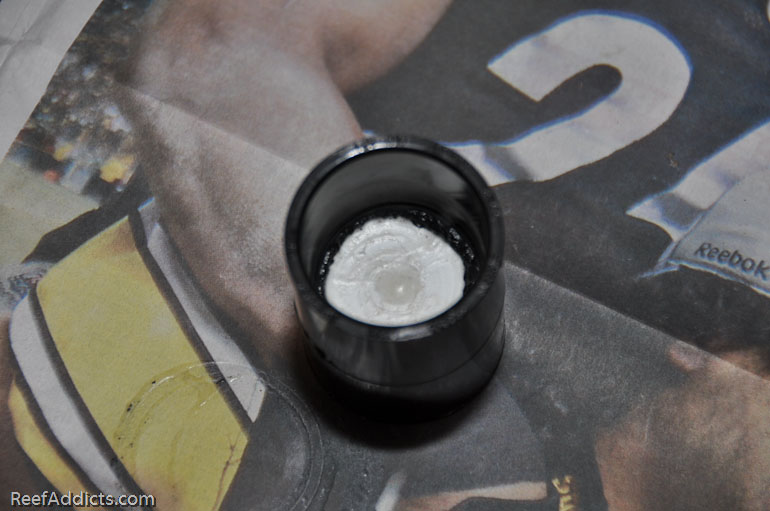
I needed that white fitting to slide into the black coupling. The thicker rim needed to be sanded away to all the fitting to seat within.


The plumbing from the Dart pump is 1.5" in diameter. Running 1.5" to the center of the return assembly, it had to then reduce to 1" PVC. The adaptors didn't come in black, so I had to paint the area that would be visible, but not paint where it would be glued. Masking off those areas was key. The fittings were painted, allowed to dry overnight and were ready the next day.
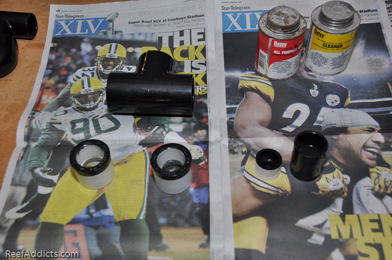


Here it is, just about ready to glue.


The Dremel'ed fittings were glued into the couplings, and painted at the same time.


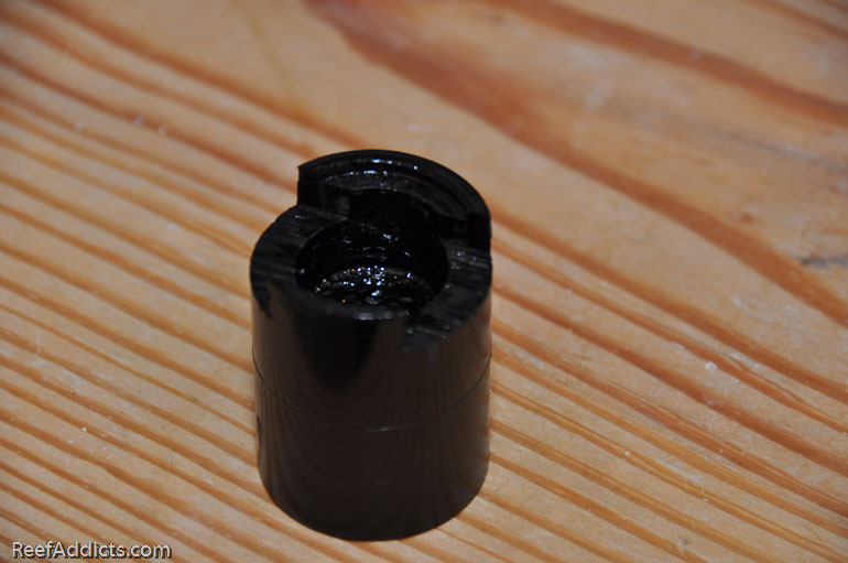
Notching them for the 1" eurobracing wasn't fun and took some time. I don't have any pictures of that since I was busy watching that I didn't lop off any of my fingers running the end piece across the table saw about 10 to 15 times to create the perfect gap or notch. It was then painted again where the white was revealed.


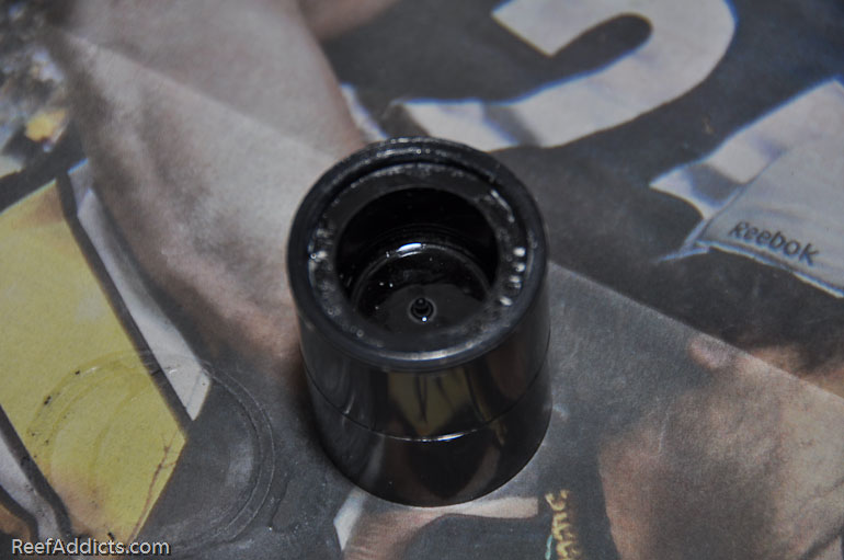
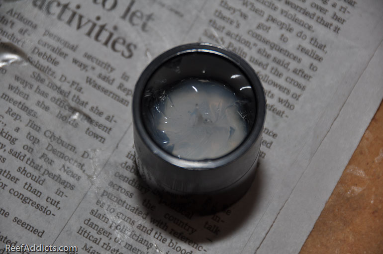
To assure that no water would weep out of this part of the assembly, I filled it with silicone prior to gluing it.


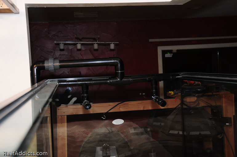
Now it is taking shape, giving you a much better idea of what I'm building. You can see small sections of 1" pipe that was cut to glue between each of the Tee fittings.


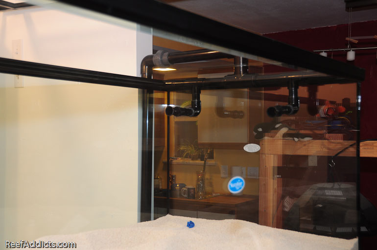
The penductors have to be submerged about 2.5" beneath the water's surface to avoid sucking in air.


I used a union in case I have to remove the assembly in the future.


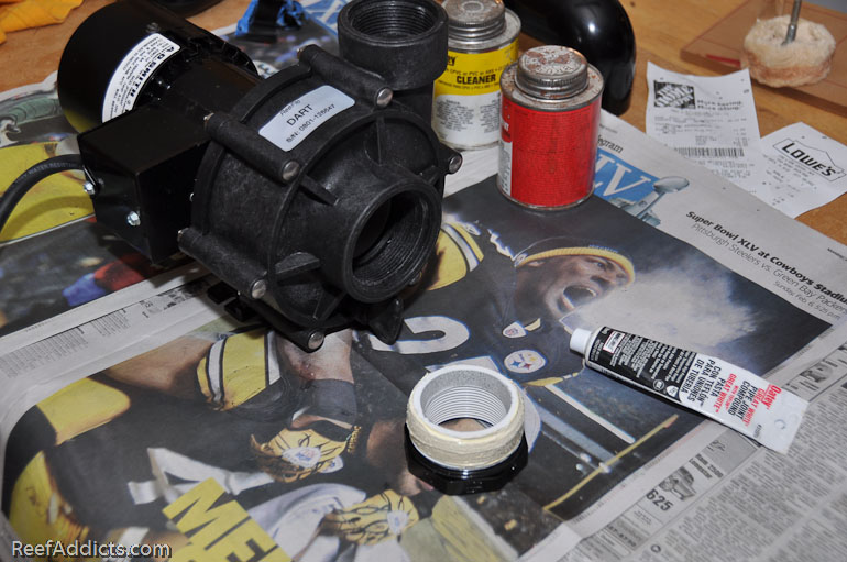
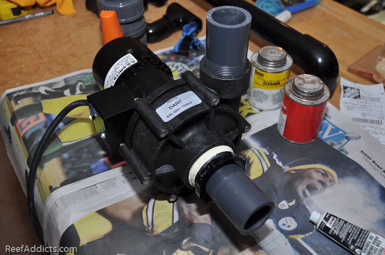
With the assembly done, let's focus on the plumbing going into and out of the Dart pump. This can be challenging. The Dart's intake is 2" in diameter, and it is a threaded opening. The output side is 1.5", threaded. I called up their toll free number to discuss the two sizes to find out if there was a reason why it was 2" going in. I was told that as long as the "in" is the same as the "out", there's no problem and cavitation won't occur.


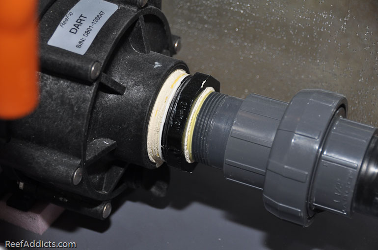
I painted a 2" to 1.5" adaptor to screw into the intake side.


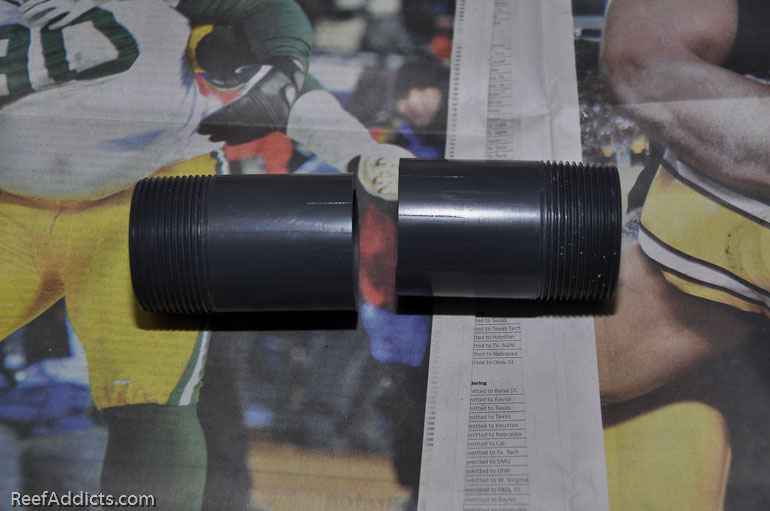
Two 1.5" (6" long) nipples were purchase from Savko.com for the express purpose of plumbing in two Dart pumps. By cutting the nipple in half, you end up having a threaded/slip fitting for both sides of the pump.


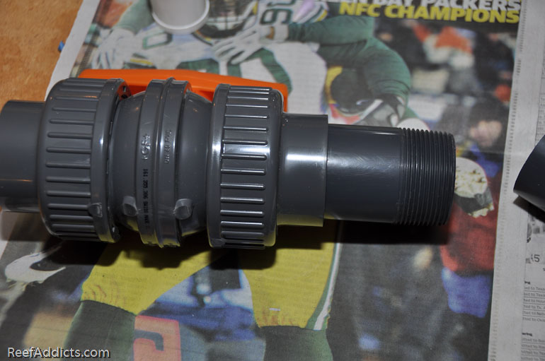
The threaded side screws into the pump, and the slip fitting glues into the union / double-union ball valve.


All threaded sections were wrapped with teflon tape and then a layer of teflon paste, and the slip fittings were primed and glued.


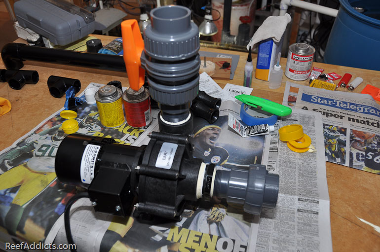
With this section fully assembled, it was ready to be installed by the sump.

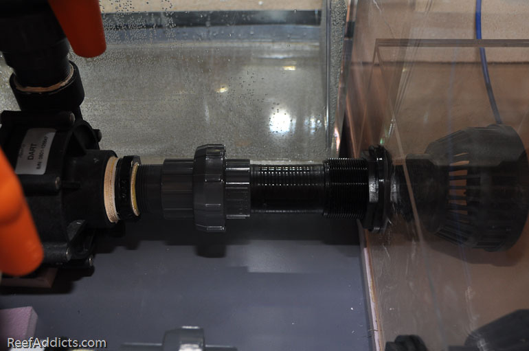
A 6" piece of black 1.5" SpaFlex was glued between the bulkhead and the union. Please note: When gluing SpaFlex, it takes longer for this to cure. After the tubing was glued into the bulkhead and the opposite end in the union section, it was left to cure overnight before I connected it to the pump. If this process is rushed, the tubing can pull lose from the fitting instead of getting a solid purchase on the PVC. Avoid applying pressure to these areas; give them time to cure before proceeding.


The union allows me to remove the pump for servicing or to change it out for another one.


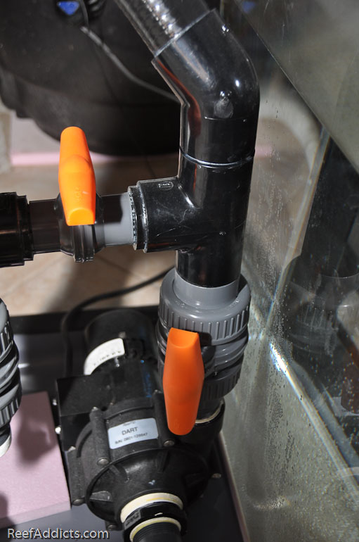
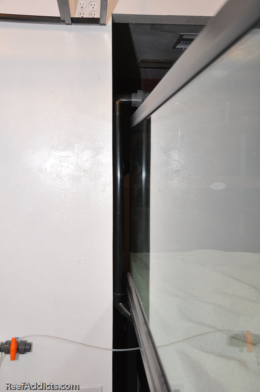
On top of the DUBV (double union ball valve), a Tee fitting and a 45 degree fitting points upward. Black SpaFlex tubing then runs upwards to the next section of plumbing. It was my best option. It is a little forgiving if the fittings aren't lined up perfectly, and removes vibration issues from the pump & plumbing. Ignore that orange handled valve to the left in the next image, as that will be explained later.


Using another 45 degree fitting, the plumbing now points upwards.


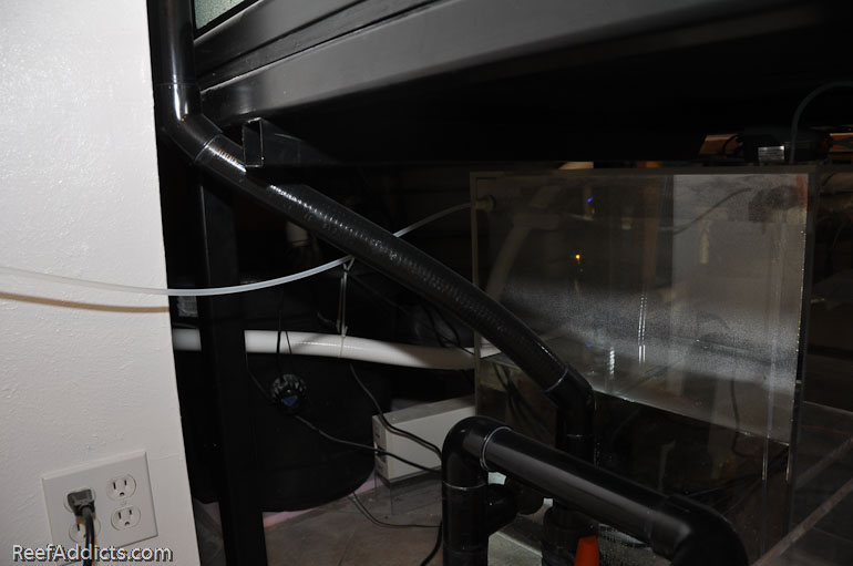
This section of return plumbing uses rigid 1.5" black PVC to hug the wall adjacent to the tank.


And that's it. It's a straight run from the Dart pump to the assembly, and I'm expecting decent flow.

Submit "Plumbing: Return assembly with Penductors" to Digg Submit "Plumbing: Return assembly with Penductors" to del.icio.us Submit "Plumbing: Return assembly with Penductors" to StumbleUpon Submit "Plumbing: Return assembly with Penductors" to Google

Updated 01-29-2011 at 05:03 AM by melev

Categories
Plumbing

Comments

  1. Reefkpr's Avatar
    Nice work!
    Q: I don't see a gate valve between the sump and pump inlet... How are you going to keep water in the sump should you need replace your return pump?

    Cheers!

    Reefkpr
  2. dahenley's Avatar
    on mine, i just reach my hand in the sump, and i have slip bulkheads, and just pop a plug in it. (he will have to remove the strainers but its that easy. then you just have the water thats in the pump itself and thats all. if you have a threaded bulkhead, then keep a threaded plug with teflon ready. (i keep a plug of every fitting in my stand, that way i have threaded and smooth plugs ready for any incident. it prevents having to run to your homecenter at weird times in your PJ's........)
  3. Jnarowe's Avatar
    That is ******* cool.
  4. brotherd's Avatar
    The mystery of how to do my return has been solved! friggin brilliant!
  5. melev's Avatar
    As dahenley stated, I'll remove the strainer and screw in a temporary plug when I have to remove the pump.
  6. rarelyseriousb's Avatar
    I have never thought of using a plug instead of a valve there. Good way to save space and money
  7. melev's Avatar
    A valve would have been much easier. Had I done that, I would have sawed off the handle though.

    Oh, you mean at the bulkhead prior to the return pump? I thought you were talking about the ends of the Penductor Assembly.
  8. Padrino's Avatar
    Hey mark,
    Great to finally meet u at macna this year, question for you


    The union allows me to remove the pump for servicing or to change it out for another one.

    If you remove that pump, how will you stop the sump from draining? I would have thought a true union ball valve would have been better for maintenance? no? or was space a factor??
    Rob
  9. melev's Avatar
    It was a money choice. Each 1.5" TUBV cost $35, and I didn't feel like spending another $70+ for that spot. Instead I have two 1.5" threaded plugs that screw in to the bulkheads where the strainer baskets are. I unscrew one basket & nipple and screw in the plug (wrapped in teflon tape). Simple, and cost me about $1.
  10. Padrino's Avatar
    touche!

    good idea!

    What did you paint your plumbing with? Krylon Fusion?
  11. melev's Avatar
    Yes, when necessary. However, I bought a lot of black pvc and fittings.
  12. Padrino's Avatar
    where do you buy black pvc and fittings, I've only seen white and grey
  13. melev's Avatar
    Flexpvc.com & savko.com were my two sources.
  14. briight's Avatar
    We are planning to put a penductor assembly into our 125g display/100g sump system. Our tank is arranged as a peninsula, with the right short side against the wall. We have two overflows, because when we purchased the first and installed it we were not happy with the amount of flow to and from the tank, and installed another beside it. The overflows are located on the back (long) side of the tank, closest to the (short)wall-facing end of the tank. The return is also there, closest to the wall. Our sump is in the basement, with a Little Giant 4 MDQ(can't remember the whole saltwater model number) pump to push the water back up to the tank. We get pretty good velocity at the return entry to the tank, but I would like to be able to direct the flow around the tank and introduce more chaotic water movement. Some places in the tank have slower, more laminar flow, and our corals have been placed accordingly. We have no other circulation pumps in the tank, and I've been trying to find a way around putting any in there if at all possible.
    We have experimented with different configurations of the return and I want to try the penductors. We have 1" pipe, and I am planning on using 1" penductors.
    My questions: Did you feel that you got enough water flow volume runnning from the pump through the two penductors to move water through the tank at the required gph rate? If there was anything you would change about the penductor assembly, what would it be and why?
    Thanks Mark!
  15. melev's Avatar
    For the most part, it worked exactly as predicted. I didn't like that my anti-siphon holes created super jets (due to the backpressure of the penductors) that had to be dealt with. I ended up installing a blast shield beneath them to deflect that directional output. I was told by one or two people to use a check valve in reverse on the return line, somewhere over the tank. The idea was that when the pump was on, the water pressure would force the check valve closed, and when the pump was off and the siphon began, it would suck open that flapper in the check valve.

    This would require that I install the check valve over the tank somewhere, because when the pump first starts some water would come out until the flapper shut fully. At the time I didn't want to look at that over my tank, but with the rebuild I may give it a shot this time.

    Besides that minor issue, it worked great and I was very pleased with the flow. In this picture, you can see the surface movement was quite chaotic, no real pattern to it.